Learn to draw shear force and moment diagrams using 2 methods, step by step. We go through breaking a beam into segments, and then we learn about the relatio
CBSE Class X 2022 Results Announced – ODM Public School Dominates the State Rankings with 100% School Results – odmps blog
Stepby-Step Solution. Step 1. We are given the load P = 10 kN/m P = 10 k N / m, moment M = 20 kN⋅ m M = 20 k N ⋅ m and force is F = 15 kN F = 15 k N. We are asked to draw the shear and moment diagrams. Step 2. The reaction force on the load is calculated as: R = P ×d1 R = P × d 1.
Source Image: chegg.com
Download Image
As a convention, the shearing force diagram can be drawn above or below the x -centroidal axis of the structure, but it must be indicated if it is a positive or negative shear force. Bending Moment Diagram This is a graphical representation of the variation of the bending moment on a segment or the entire length of a beam or frame.
Source Image: hacettepeaso.hacettepe.edu.tr
Download Image
Solved Draw the shear and moment diagrams for the beam, and | Chegg.com Plots of V(x) and M(x) are known as shear and bending moment diagrams, and it is necessary to obtain them before the stresses can be determined. For the end-loaded cantilever, the diagrams shown in Figure 3 are obvious from Eqns. 4.1.1 and 4.1.2. Figure 4: Wall reactions for the cantilevered beam.
Source Image: chegg.com
Download Image
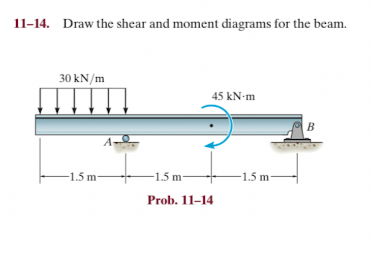
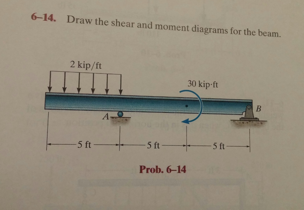
6-14 Draw The Shear And Moment Diagrams For The Beam
Plots of V(x) and M(x) are known as shear and bending moment diagrams, and it is necessary to obtain them before the stresses can be determined. For the end-loaded cantilever, the diagrams shown in Figure 3 are obvious from Eqns. 4.1.1 and 4.1.2. Figure 4: Wall reactions for the cantilevered beam. Shear force and bending moment diagrams are analytical tools used in conjunction with structural analysis to help perform structural design by determining the value of shear forces and bending moments at a given point of a structural element such as a beam. These diagrams can be used to easily determine the type, size, and material of a member
Solved 6-14. Draw the shear and moment diagrams for the | Chegg.com
164K subscribers Subscribe Subscribed 669 Share 89K views 3 years ago Statics This is an example problem that will show you how to graphically draw a shear and moment diagram for a beam. Shear Force and Bending Moment Daigram Examples PDF | PDF | Bending | Civil Engineering
Source Image: scribd.com
Download Image
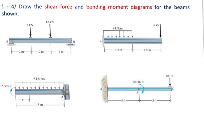
Solved) – Draw the shear force and bending moment diagrams for the beams… – (1 Answer) | Transtutors 164K subscribers Subscribe Subscribed 669 Share 89K views 3 years ago Statics This is an example problem that will show you how to graphically draw a shear and moment diagram for a beam.
Source Image: transtutors.com
Download Image
CBSE Class X 2022 Results Announced – ODM Public School Dominates the State Rankings with 100% School Results – odmps blog Learn to draw shear force and moment diagrams using 2 methods, step by step. We go through breaking a beam into segments, and then we learn about the relatio

Source Image: odmps.org
Download Image
Solved Draw the shear and moment diagrams for the beam, and | Chegg.com As a convention, the shearing force diagram can be drawn above or below the x -centroidal axis of the structure, but it must be indicated if it is a positive or negative shear force. Bending Moment Diagram This is a graphical representation of the variation of the bending moment on a segment or the entire length of a beam or frame.
Source Image: chegg.com
Download Image
Untitled Apr 2, 20237.38K subscribers Subscribe Subscribed Share 2.3K views 8 months ago UNITED STATES 6-41. The compound beam is fixed at A , pin connected at B , and supported by a roller at C . Draw the
Source Image: hacettepeaso.hacettepe.edu.tr
Download Image
6-42 Draw the shear and moment diagrams for the compound beam | Mechanics of Material Rc Hibbeler – YouTube Plots of V(x) and M(x) are known as shear and bending moment diagrams, and it is necessary to obtain them before the stresses can be determined. For the end-loaded cantilever, the diagrams shown in Figure 3 are obvious from Eqns. 4.1.1 and 4.1.2. Figure 4: Wall reactions for the cantilevered beam.

Source Image: m.youtube.com
Download Image
Drawing Shear and Moment Diagrams for Beam – YouTube Shear force and bending moment diagrams are analytical tools used in conjunction with structural analysis to help perform structural design by determining the value of shear forces and bending moments at a given point of a structural element such as a beam. These diagrams can be used to easily determine the type, size, and material of a member

Source Image: m.youtube.com
Download Image
Solved) – Draw the shear force and bending moment diagrams for the beams… – (1 Answer) | Transtutors
Drawing Shear and Moment Diagrams for Beam – YouTube Stepby-Step Solution. Step 1. We are given the load P = 10 kN/m P = 10 k N / m, moment M = 20 kN⋅ m M = 20 k N ⋅ m and force is F = 15 kN F = 15 k N. We are asked to draw the shear and moment diagrams. Step 2. The reaction force on the load is calculated as: R = P ×d1 R = P × d 1.
Solved Draw the shear and moment diagrams for the beam, and | Chegg.com 6-42 Draw the shear and moment diagrams for the compound beam | Mechanics of Material Rc Hibbeler – YouTube Apr 2, 20237.38K subscribers Subscribe Subscribed Share 2.3K views 8 months ago UNITED STATES 6-41. The compound beam is fixed at A , pin connected at B , and supported by a roller at C . Draw the